ROTSE-III hardware manual
Version 1.0 08-Apr-2008 mcba, added info on Dec
encoder replacement,
collimation of the secondary mirror (including
focus model comments from Fang Yuan), and
a quick guide to some aspects of "rush"
Version 0.9 04-Feb-2006 mcba, added info/photos of the new cam3a
computer
Version 0.8 25-May-2005 mcba, added photos of the CCD camera boards
Version 0.7 18-Jan-2005 mcba, added Vaisalla precipitation detector
information
Version 0.6 29-Oct-2004 mcba, added oscilloscope traces for the gold box
Version 0.5 24-Sep-2004 mcba, lots of additions, particularly the servo
slipping/oscillation detection software
Version 0.4 28-Oct-2003 mcba, added links to images of ROTSE-IIIa
cable routing.
Version 0.3 07-Oct-2003 mcba, added fix for oscillation when homing.
Version 0.2 08-Aug-2003 mcba, added optical collimation section.
Version 0.1 05-Aug-2003 Michael Ashley, assisted by wisdom extracted
from e-mails by Alan Schier, Carl Akerlof, Eli Rykoff, Andre Phillips.
and Jim Wren.
See also, Andre's
fault-log page
Checklist of known problems, and what you should do to protect your
mount/telescope
- A drive motor can overheat due to excessive current over a
prolonged period of time (>30 minutes?). The motor will partially
demagnetise due to the temperature, and will therefore have reduced
performance from then on, making it more likely to overheat in the
future. Solution: install a thermostatic cutout switch on the motor body; ensure I2t (current-squared times time,
i.e., heating) protection is enabled in the
mount software; check the balance of the telescope, and look for cable
snags.
- The
drive capstans can be shredded, and the capstan then grinds into the
drive wheel. Solution: install Andre's protection widgets, or similar
devices, on both RA and
DEC axes; replace the capstans; adjust the
preload
and servo coefficients
appropriately;
repair the damaged metal surfaces with gentle application of, e.g.,
Scotch-Brite (take great care not to damage the encoder tapes). See
also this additional information.
- Misshapen images out of focus. Solution:
consider reducing the tension on the primary
mirror retaining screws. Other possibilities are wind
vibration, servo oscillation or collimation errors.
- A "thump" is heard as the mount slews. Solution:
it is possible that the RA and/or Dec axes are loose, consider adjusting the preloads.
- The mount oscillates at low frequencies, or with an audible whine. Solution:
the servo coefficients may need
adjusting; the drive capstans may be worn; the capstan
preloads may need adjusting.
- The mount oscillates when homing at the home limit switch. Solution:
balance the telescope so that it is
slightly
biased towards the home limit.
- The Renishaw encoder shows orange or red on its status LEDs for
part or all of the sky, possibly leading to a position error being
flagged by the mount computer. Solution: adjust the
encoder position; clean the encoder tape; inspect the RA/Dec axes for loseness.
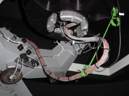
ROTSE-IIIa cable routing
Note: the green rope is critical to proper operation (i.e.,
minimal torque applied to the telescope throughout the entire range
in RA and Dec.
Click on the images for the full-resolution view.
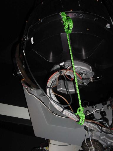
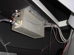
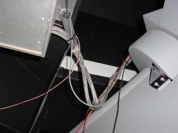
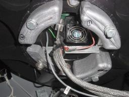
Oscillation when homing the telescope
Alan and Eli have identified a situation where the (im)balance of the
telescope will degrade the homing accuracy of the axes.
The desirable situation is that each axis shows neutral balance or be
biased slightly toward the home limit switch when the axis approaches
the switch. If this is the case, the homing should be repeatable
to a few arcminutes.
The undesirable situation is when an axis is biased to fall away from
the switch as the axis approaches the switch. This will cause the
"rocking" oscillation at the limit switch that has been observed.
The phenomenon is rooted in how the drive amplifiers are enabled and
disabled when the limit switch is tripped, and it is hardwired in the
electronics. There's no other reasonable way around it except to
balance the axis.
Adjusting the drive capstan preloads
Alan: It is not too difficult to get the preload for the drive correct.
One tightens the preload screw until the capstan does not slip when the
axis experiences a significant disturbance (like being pushed by hand).
And then maybe a half turn more. The drive surface and capstan
should be reasonably clean, but need not be spotless.
Andre comments: when tensioning the RA capstan onto the drive wheel, I
find there's a narrow range of tensions between too little (capstan
skids) and too much.
The Dec drive seems to be less touchy about the
capstan<->drive-wheel tension.
Possible causes for shredding of the RA
and Dec drive capstans
- The mount computer is running, but the servo software is not
running.
- The brakes are applied.
- Excessive current to the motor, causing slipping.
- The capstan preload may be low enough that the drive slips under
the steady application of torque. Once large-scale slipping starts, the
drive can shred the capstans in a matter of seconds.
- Violent oscillation of the capstan due to inappropriate servo
coefficients, or a gradual change in the drive characteristics (e.g.,
once the capstans wear, the rate of wear is likely to increase).
Preventing damage of the drive following
capstan wear
If the rubber coatings are sufficiently damaged, the metal capstan can
make
contact with the drive wheel, and eat its way into it, causing
substantial damage. To prevent this, you can install Andre's protection
widgets. Here are some images of them
on the ROTSE-IIIa telescope (which uses a different RA motor to the
other telescopes). An alternative is to use a stop-screw next to the
preload spring (Alan is designing one for ROTSE-IIId, and Dmitry has
made one for ROTSE-IIIb).
Setting the mount servo
coefficients: Kp, Ki, Kd
The ROTSE motors are stabilised by a PID (proportional, integral,
differential) feedback loop. The three coefficients Kp, Ki, and Kd,
have
to be set appropriately in order for this loop to be stable under all
conditions. The position encoder is a Renishaw tape mounted on the axis
drive wheel. If anything changes in the mechanical part of the loop
(e.g., o-ring wear, bearing preload), then this can affect stability.
Here is a prescription for setting initial values for Kp, Ki, and Kd,
from Alan Schier:
- Note the existing parameters (Kp, Ki, Kd) so that you can restore
them if needed.
- Put 2 and 0.4 in the f and z box respectively in the "Calculate
Gains from Break Frequency and Damping" box and click the calculate
button.
- Copy the resulting Kd and Ki value to the servo parameters for
the axis of concern.
- Lower Kp for that axis to maybe half of its current value.
- With the servo running (axis in the "Stop" state, probably),
raise Kp as described previously. That is, perturb the axis while
raising Kp until the servo oscillates and then lower Kp until the
oscillation stops.
This will leave the servo in a reasonably robust state.
If you want to push the envelope and make the servo more "aggressive",
start rasing the break frequency value from 2 to 3 or 4, recalculate
the
values of Kd and Ki. (In this case there is nothing to gain by changing
the damping, z.) Copy the new values to the servo parameters and
then readjust Kp again. What you will find is that the servo
becomes "stiffer", and the range of acceptable Kp values will
narrow. That is, the range between where Kp is too low
(sub-audible low frequency servo oscillation) and too high (audible
oscillation) becomes smaller. Eventually the range disappers
altogether,
and you will not be able to make the axis stable by adjusting Kp.
When you do this, you are moving the roots around in the complex plane
of the chacteristic equation that describes the system dynamics.
Some root positions are better than others. Roots in the right
half of the complex plane are unstable. Roots in the left half
are
stable and have a continuum of performance characteristics ranging from
"twitchy" to "sluggish".
The break frequency and damping describe the position of a complex pair
of roots over which we have direct control. The other roots are
controlled less directly since they are determined by the mechanics of
the system. In a sense, Kp is our remaining handle on those roots.
A further note: beware if you start to adjust Kp, Ki, and Kd by
simply observing the perfomance of the axis and changing one or
another. The stable combinations of these three exists is a space
in which they are surrounded by combinations that are unstable.
In
particular, if you start with all of them near zero, you will have to
traverse unstable territory to get to anything that performs well at
all.
Here are some additional notes from Alan on adjusting Kp in the event
of mount oscillation:
- Lower the Kp gain by 60%. Push on the RA axis with
your hand and watch the resposne. The servo should still be
stable. The axis may have a sluggish response and recover with a
bit of overshoot. This is normal.
- Start raising the gain with the little up arrow at the right side
of the Kp box. The axis's response to a push will become faster
and the overshoot will decrease.
- Keep raising the gain and listen/feel for an oscillation to start
as you keep perturbing the axis with your hand.
- Once you get an oscillation, quit pushing on the axis and start
lowering the gain by clicking on teh down arrow until the oscillation
stops by itself. That's the right place to leave the gain.
Some general notes:
- If the capstan slips when you push on the axis, tighten the drive
preload.
- If the Kp gain is too low, the axis will oscillate with a low
(sub-sonic) frequency.
- If the Kp gain is too high, the axis will oscillate with a high
(audible) frequency.
- There's usually no need to fiddle with Ki or Kd. They set
the position of a couple poles in the transfer function, and those
shouldn't need changing. The same goes for the filter
coefficients, only more so.
Andre notes that a good way of getting a feel for the system is to grab
the tail of the motor shaft that protrudes from the rear of the servo
motor and twist it abruptly this way and that. Andre noted some slight
"springiness" in the capstan drive shaft, deriving from the
helical coils in the shaft coupler. These are the coils that Alan
has partially filled with modeling putty in order to reduce vibration.
The following table shows the coefficient values at the indicated dates
(note that ROTSE-IIIa has a different RA motor from the other sites).
See also the servo.ini section below.
|
Kp (RA/Dec)
|
Ki (RA/Dec) |
Kd (RA/Dec) |
ROTSE-IIIa at 2003 Aug 14
|
27.273 / 8.743
|
15.708 / 10.472
|
0.06 / 0.066
|
ROTSE-IIIb at 2003 Oct 30
|
15.408 / 8.744
|
10.472 / 10.472
|
0.066 / 0.066
|
| ROTSE-IIIc |
Eli?
|
Eli? |
Eli? |
| ROTSE-IIId |
?
|
?
|
?
|
The server loop runs with a 2millisec period on a Windows NT computer.
The period can be varied in the servo.ini file, but Alan Schier can't
think of a good reason to do so. He comments "it can run as fast as 1
ms, but the low-frequency dynamics of the controller become numerically
sensitive at that point."
Anti-slip and anti-oscillation software
Michael wrote some modifications to Alan's code to include slip and
oscillation detection. Eli got this working on ROTSE-IIIb, and the aim
is to have it working on all sites. The code involves some new
parameters in the servo.ini file. Here is how it works:
Slipping
Slipping is
regarded as occurring if the following two conditions are met: the
absolute value of the axis velocity is less than a user specified value
(m_fAxis1SlipVelocityThreshold), and the absolute value of the axis
output voltage is greater than a user specified value
(m_fAxis1SlipVoutThreshold), i.e., we are driving the axis motor, but
the final shaft isn't moving. If these conditions occur for
m_fAxis1SlipCountThreshold consecutive servo cycles, then a slip fault
is set.
To establish values for the parameters, begin by deciding the maximum
time in seconds you can tolerate a slipping condition. This might be
0.3 seconds. Then set m_fAxis1SlipCountThreshold to this time divided
by the servo period (normally 2 milliseconds), e.g., 150. Now choose
the velocity (in encoder counts per servo cycle (I think)) below which
the shaft is regarded as being almost stationary; for guidance, the
fast home speed is about 75000, the slow home speed is about 1000; so
perhaps a value of 1000 is essentially stationary. Now choose the
output voltage threshold, m_fAxis1SlipVoutThreshold, above which it is
assumed that the shaft should be turning, this value should be greater
than any holding torque.
Actually, it might be best to measure the real performance of the
mount, and try to set parameters which will detect any obvious
deterioration in the performance.
To disable the slippage detection for the RA axis, set
m_fAxis1SlipCountThreshold to zero in the servo.ini file. For Dec,
change the 1 to a 2.
Oscillation
The test for oscillation is
based purely on examining the time behaviour of the axis output
voltage. The peak-to-peak amplitude of the voltage is determined over
an interval of m_nAxis1OscillationMaxCount servo cycles. This amplitude
is then squared and added to a decaying sum of all the previous
amplitudes squared. If this decaying sum exceeds the critical number
m_fAxis1OscillationFaultThreshold, then a fault condition is set.
In order to detect oscillation at a variety of frequencies, the
calculation is done over NUMFREQ different numbers of servo cycles. For
each frequency the user has to specify the following parameters:
m_nAxis1OscillationMaxCount[i] - the number of servo cycles over which
to calculate the amplitude. If this is zero, the calculation is skipped.
m_fAxis1OscillationDecay[i] - the decay constant to apply to the sum of
amplitudes
squared.
m_fAxis1OscillationFaultThreshold[i] - the threshold at which a fault
condition is set.
To disable the oscillation detection for the RA axis, set
m_fAxis1OscillationMaxCount[i] (for i equals 0 to 4) to zero in the
servo.ini file. For Dec, change the 1 to a 2.
Servo.ini files
The mount computer software reads a file called servo.ini when it
starts. This sets various parameters. Here is servo.ini for ROTSE-IIIa at 2005 Sep 30
And here is servo.ini for ROTSE-IIIb on
2004 Mar 18.
Measured axis torques
Andre says on 2003 Jan 15 (prior to the installation of a smaller RA
capstan): I made some measurements by applying measured torque to the
RA/Dec axes and comparing this with the servo correction voltage (as
displayed on the GUI). Using a small set of 'fisherman's' scales
I tugged at the telescope from different directions with different
forces and was pleased to note that the results were fairly
consistent. That is, for the RA axis, the servo correction
voltage is around 1.7V/pound.foot (+/-10%) = 1.3V/N.m. For
interest, the detente torque (RA motor engaged, power off) is ~2.1
pound.foot.
Out of interest I compared this with the response of the Dec motor and
got 0.8V/pound.foot (+/-10%) = 0.6V/N.m ; about half the RA
figure...which is interesting as it explains why it's so easy to go
overvolts on the RA and not the Dec. Dec detente torque is ~2.5
pound.foot.
Note that the above voltages are "as displayed on the GUI", not "as
applied to the motor". At the RA motor, the real voltage and current
torque figures are 0.4V/pound.foot and 1.1A/pound.foot.
The meaning of the GUI voltage reading
The voltage you see on the screen for the servo control is not the
voltage that is applied to the motor. It is the voltage that is
applied to the drive amplifier. The amplifier turns that voltage
into a current that ranges between +/-6 amps, which is what is then
applied to the motor. For the ROTSE-IIIa RA motor the ratio of the Vgui
voltage, versus actual measured motor terminal voltage is around 3
(+/-15%).
Motor specifications
The ROTSE-IIIa RA motor is a GPM16LR pancake motor
(http://www.pmlflightlink.com/gpseriesfrms.html). These specifications
also show that the continuous-stall current for this motor is an
impressive 8amps, or a terminal voltage of ~3.4V.
Mount limit switches
If the telescope reaches the first limit, the drive amplifier is
inhibited from driving further into the limit. It can still drive
out of the limit. If this isn't working, something's amiss in the
electronics.
Renishaw encoder
The specification for the RGH22-Y30D00 encoder head is for a maximum
runout of +/-0.1 mm, which is comfortably greater than the measured
runout of the ROTSE-III mounts. See the Renishaw
RGH22 data sheet, the installation
guide, and the DXF
drawing, for more information on the encoder.
The encoder head is sensitive to the yaw angle relative to the scale,
and less sensitive to the pitch and roll angles. If the yaw angle
is off, the encoder will not tolerate the full +/-0.1 mm range of
runout. If the light is turning red in places, move the axis just
to the edge of the red zone (the light may be orange) and poke the
encoder mount with your finger in the yaw direction. If you can
make the light turn green, that means the yaw angle could be
improved. For that matter, you can poke the mount in the other
directions as well to see if other adjustments would help.
Andre remarks: most of today I've been fiddling with the RA-axis
Renishaw encoder. I was mostly adjusting yaw and could get things
mostly right, but never consistently so. Then I decided that
guesswork was out and removed a lead weight and the lower aluminium
'bumper' bracket so that I could get vernier calipers around the sensor
and find out what was really going on. Thus exposed, it's
relatively easy to measure the yaw by measuring for parallelism of the
sensor with the overhead drive wheel. The correct 0.8mm spacing
from the graticule was achieved with a paper 'feeler gauge' (by a
convenient coincidence, our standard photocopy paper thickness is
0.10mm). Then I measured the roll (i.e. parallelism with the
tangent to the drive wheel) and was surprised to find it
off-by-a-country-mile (i.e. 2.3 degrees). This was corrected and... hey
presto... solid green status light all the time, no red/orange
flickering, no exceptions.
The moral of the story is that these encoders are very sensitive and
have to be set up precisely
to
spec, and trying to 'wing it' by simultaneously adjusting three
free-parameters is not the optimum way of doing it. Getting
down-and-dirty with measuring gear is the best method, even if it means
stripping the telescope down a bit to get the micrometer into
position.
The RA Renishaw encoder sits on an aluminium block heater. There is a
heater and thermocouple in that location. If you look at the
servo
control panel, you'll see the temperature monitoring/control info
toward
the lower left. The servo software monitors the temperature to
keep the block above 0 C (or whatever setpoint is set in the control
panel). The encoder heads are specified to 0 C. Below that, the
LED output declines. If properly aligned, they will work below 0 C (to
-10 C at least). If the alignment is marginal, the status light
will turn red.
Right ascension bearing adjustment
There is a nut on the lower end of the RA axle that bears against a
wavespring and the brake wheel. These items bear against the
inner
race of the lower bearing and provide tension to keep the fork snug
against the inner race of the upper bearing.
The preload nut is the ring at the center of the brake wheel.
First loosen the 1/4-20 set screw on the hub of the brake wheel.
1/2 to 1 turn should be enough. Then tighten the nut until it is snug
using a spanner wrench or a couple of punches placed in the holes for
the spanner wrench. The bearings are hugely oversized for the
load
they carry, and there is little danger of overtightening.
When things are snug, you should notice an appreciable increase in the
friction when you rotate the RA axis. If the friction hasn't
increased, the upper bearing is probably still loose. You could
monitor the position of the RA drive wheel relative to the base using a
dial indicator. If the axle was loose, you will see the drive
wheel settle back toward the base when you tighten the nut. Once this
is
done, you can loosen it just a bit. About 30 degrees is fine.
This
allows the wavespring to expand a bit. You can then tighten the
set screw on the brake wheel, and that should be it.
The bearings are tapered rollers.
What should the maximum runout be on the RA drive wheel? Alan's
recollection of the ROTSE-IIIa mount is that it had no more than
+/-0.04
mm (+/-0.0015") of runout on the drive wheel. Alan measured another
mount and found it is within +/-0.02mm (+/-0.0075") except for near a
machining ding that is outside the encoder area. Including that
ding, it would be about about +/-0.04 mm.
Declination bearing adjustment
The bearings on the drive side of the dec axis are an opposed pair of
roller bearings and are preloaded with wave springs on the
inside.
The bearing on the other side is a single roller bearing on the outside
portion of the axle with a wave spring under the nut (on the outside).
If the bearings are loose, a "thump" might be heard as the axis settles
depending on the telescope position.
The way to adjust the bearing is:
- Loosen the non-drive side a bit. Two or three turns on the
nut should suffice.
- Tighten the drive side nut until you flatten the preloading wave
spring. You'll feel the tightening torque increase suddenly when this
happens.
- Back the drive side nut off about 1/8 turn.
- Tighten the non-drive side nut until the wave springs are
flattened. This may take considerably more torque that for the drive
side since the preload on this side is larger.
- Back off the non-drive side nut about 1/8 turn.
That's it. The bearings are oversized for the task and very
robust. There's no need to be particularly ginger when tightening the
nuts.
Andre commented: unlike the RA bearing adjustment, I can easily see the
Dec bear adjusting nuts and wave springs. On the motor-drive-side
I noted see that the wave spring was looking nearly fully squished, but
on the non-drive-side, somewhat less squished. So I progressively
tightened the non-drive-side adjustment, and after at about
half-a-turn,
the "thump" disappeared.
Motor protection
The servo motors can be driven with quite high voltages (>10V) for a
short amount of time (a minute or so) in order to produce large
accelerations. However, they can only withstand 2 or 3V continuously
before they will overheat (on a timescale of perhaps 30 minutes). The
mount control computer will register a fault condition if either a high
voltage is applied for more than a user-defined number of seconds, or
the integrated power to the motor (measured by integrating the current
squared) exceeds a user-defined threshold. To prevent the "High Output
I^2" fault, you need to ensure that the mount is carefully balanced and
that there is no excess friction from, for example, snagging cables.
Thermostatic protection of the servo motors
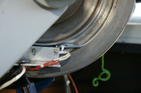
At ROTSE-IIIa we have installed thermostats on the RA and Dec motors to
provide a last line of defense against motor overheating (which has
burned out at least three motors in ROTSE-IIIa/b). The thermostat we
used is a normally-closed encapsulated type, with a setpoint of
50C. This image shows the
thermostat topped with a gob of heat conductive paste, and set into a
foam-plastic 'blanket'. This
image
shows the thermostat strapped onto the side of the motor, and connected
in series with it. These particular thermostats have a hysteresis
of around 10C, so if the thermostat is tripped, it will take some time
for the motor to become reconnected. Note that this addition
doesn't interfere with the removal of the Dec drive wheel cover.
Primary mirror cell adjustments
The radial restraint is via four rather broad arcs, although as a
practical matter, the contact will be localized to a region in the
center of the arcs as the arcs are relatively compliant. The arcs
bear on the rear of the mirror. The arc material and dimensions
are chosen such that the system is athermal for uniform
temperature--they are not spring loaded. After the mirror is
installed, the arcs are adjusted such that they are in contact with the
mirror and are left there. Should this arrangement ever put the
mirror into a bind, it would be apparent as astigmatism in the image.
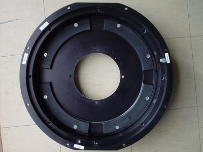
The following image shows the primary mirror cell, with the mirror
itself removed. The four arcs bear on a machined lip on the back of the
mirror, and are adjusted radially by set screws (one for each arc).
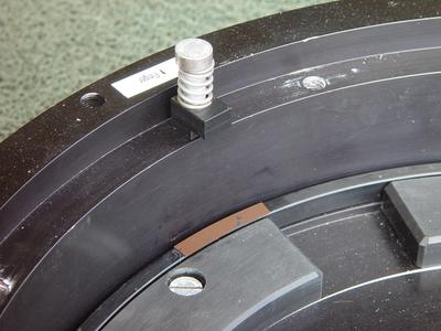
This image below shows one of the primary mirror retaining screws,
which bears down on a plastic L-shaped bracket, which in turn contacts
the edge of the mirror. The back of the mirror rests on the small brown
plastic strip visible below the bracket. It is very important that the
spring is not completely compressed (since this will allow large forces
to be placed on the mirror). It is also important that the L-bracket
and
the brown strip are aligned, and that the mirror is resting on the
three
brown strips, else a torque will be applied to the mirror.
During the commissioning of ROTSE-IIIb the three primary mirror set
screws were too tight, turning the out-of-focus doughnuts into
triangles. Adjusting the set screws 1/128 turn past contact held
the mirror nicely without distorting the shape.
Metric/imperial?
Are you wondering why there is such a bewildering mix of metric and
imperial fasteners on that unit? It's because the telescope was
designed before there was a mount for it. It turns out that the
telescope was designed using metric dimensions. When we got a
mount, it was imperial. So, use metric wrenches
if you're working on the telescope; imperial for the mount.
Adjusting the secondary support vanes
It is possible to make the vanes tighter or looser, depending on how
the secondary assembly has been installed. To tighten the vanes:
- Loosen the both ends of the two vanes whose alignments do not
pass through the center of the secondary assembly. That is, there
is one vane that is strictly radial and two other that are a bit off of
radial. So, loosen the both ends of the two non-radial vanes.
- For each of those two vanes, slide the end nearest the secondary
cylinder in a direction tangential to the cylinder. There is a
bit
of clearance in the screw holes that will allow this. Q: Which
direction to slide them (clockwise or counter-clockwise)? A: In
the direction that would tend to pull the vane away from the outer
barrel.
- Tighten the screws that attach the vanes to the secondary
cylinder.
- Tighten the screws that attach the vanes to the outer
barrel. This should tension the vanes.
Collimation of the primary mirror and optics tower
The optical design of the ROTSE-III telescope employs a parabolic
primary mirror, a flat secondary, and a multi-element optical tower.
Aligning the secondary mirror is a trivial operation, since the fact
that it is flat means that the only necessary adjustments are two tilt
axes, and these can be easily done using out-of-focus star images.
Aligning the optical tower is much more difficult, since it has to be
both centred and tilted correctly with respect to the parabolic surface
of the primary, which is not necessarily aligned with the edges or back
of the mirror. Note that it is not necessary to align the optical axis
of the system with the telescope tube, or perpendicularly to the mirror
cell, although in practice any misalignment will probably be less than
1
degree in tilt and 1 mm in displacement.
In the following procedure, we assume that the internal elements in the
optical tower are correctly aligned.
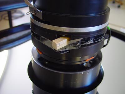
Begin by taking the primary mirror cell and optical tower out of the
telescope. Insert a wooden block to hold the shutter open, as per the
following image.
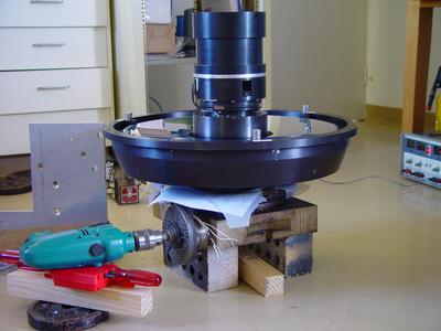
Mount the mirror cell on a dividing head
from a milling machine (see the image below). The dividing head we used
had a central hole which enabled us to inject a laser beam via a 45
degree mirror. We used a portable hand-drill to assist with rotating
the
dividing head. The next task is to align the parabolic surface of the
primary mirror as exactly as possible with the rotation axis of the
dividing head. This can take a couple of hours of trial and error with
the crude setup we used. Sheets of paper were placed under the mirror
cell in order to make fine adjustments to the tilt. We bounced a laser
beam off the mirror surface and looked at the reflection on the wall of
the room, several metres from the mirror. When the beam does not move
when the dividing head is rotated, the mirror is perfectly aligned. We
were successful in aligning the tilt to < 1 arcminute, and the
centering to better than 0.2mm. The optical access of the ROTSE-IIIa
mirror is certainly within 0.5mm of the physical centre as defined by
the edges of the mirror.
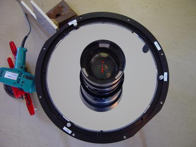
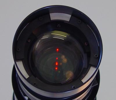
Now shine a laser through the optical tower, using a mirror at 45
degrees positioned immediately below the dividing head. It is
relatively
easy to align the tilt and decentre of the laser precisely to the
optical access of the tower by looking at the reflections of the laser
light back along the optical path (the laser reflections on the various
lenses in the tower are visible in the image below). Now spend another
hour or so adjusting the tilt of the tower so that the reflected laser
light does not move when the dividing head is rotated. You may need to
machine an allan key in order to fit the four adjustment points on the
tower. Adjustment is performed by adding/removing plastic shims. We
were
able to achieve <1 arcminute alignment after some hours of work.
However, we noticed that the laser beam passing through the optical
tower wobbled by +/-2.5 arcminutes as the tower was rotated. We suspect
that this is due to some residual misalignment of the elements within
the tower.
Enclosure
The enclosure electrical diagram.
Vaisala humidity sensor
The trigger voltage is 2.90V ("dry" is around 2.95V).
I/O box
From Jim Wren: the relays are made by IDEC and claim to be fine for
general use at 7A for 240VAC (7.5 for 120VAC). I checked the spec
sheet for the Duff Norton linear actuators and they say they draw
6.2A@115VAC and 2.0A@220VAC for the max applied load which is
1500lbs. This should be well within what the relays can handle.
Camera problems
Bob Leach has received the ROTSE-3b TEC power supply, and has found the
problem: one of the two 6.5V switching power supplies burned off
its electrical contact. This problem has happened before.
Bob has a theory of "grit" getting in there, and has replaced the
offending switching power supply, and has improved the output
connector. However, we are not sure if this is a permanent fix,
or if there is some other problem with the power supply.
Focus motor
From the manufacturers specifications:
It may be necessary to lubricate the drive screw after approximately
500 hours of continuous use. A lint free wipe should be used if
removing spent or excess lubricant from the drive screw. A suitable
lubricant can be provided by Newport upon request. (Newport part number
CMA-LUBE).
Polyurethane capstans
We have 4-pcs 65-70 black and 4-pcs 75-80 blue. Both are high
strength polyurethane poly-ether base. Purchased from
metalrubber.earthlink.net
in March 2005.
Camera firmware
Checksum of the EEPROM in the timing board is B68D.
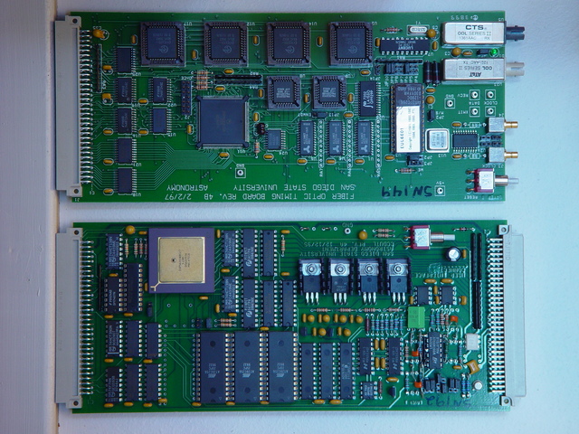
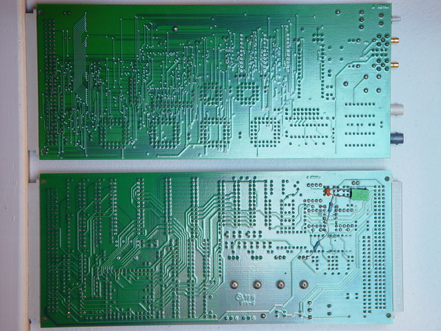
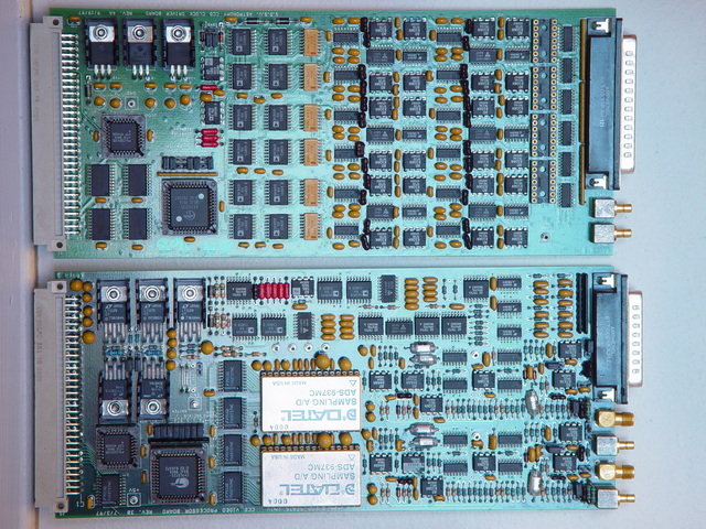
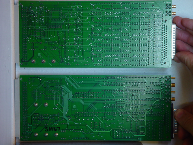
Photos of CCD boards
Click on the photos for the full resolution images.
Component view: timing board at the top, utility board at the bottom.
Solder side view: timing board at the top, utility board at the
bottom.
Component view: clock driver board at the top, video board at the
bottom.
Solder-side view: clock driver board at the top, video board at the
bottom.
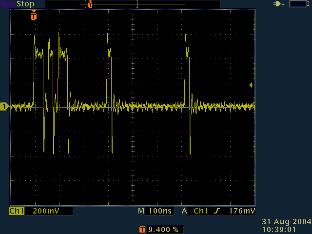
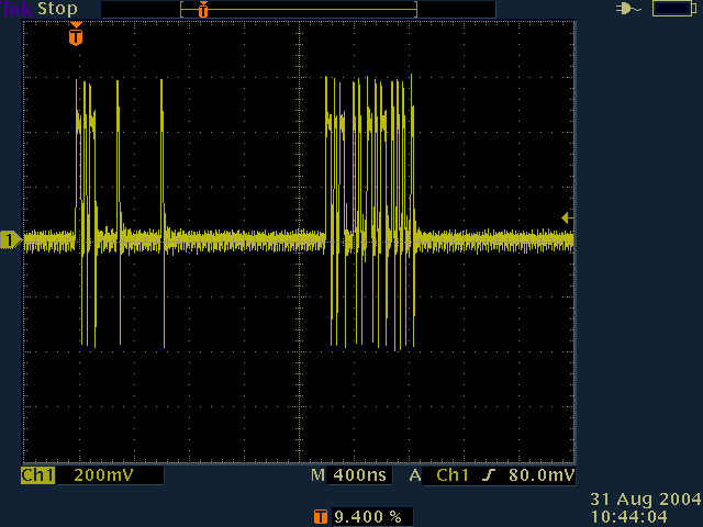
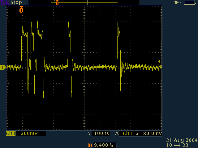
Camera oscilloscope traces
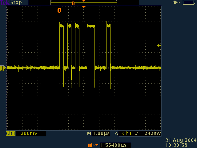
Bit patterns for status codes:
SYR     00 53 59 52 0000 0000 0101 0011 0101 1001 0101 0010
DON     00 44 4F 4E 0000 0000 0100 0100 0100 1111 0100 1110
ERR     00 45 52 52 0000 0000 0100 0101 0101 0010 0101 0010
RDR     00 52 44 52 0000 0000 0101 0010 0100 0100 0101 0010
TIMEOUT 54 4F 55 54 0101 0100 0100 1111 0101 0101 0101 0100
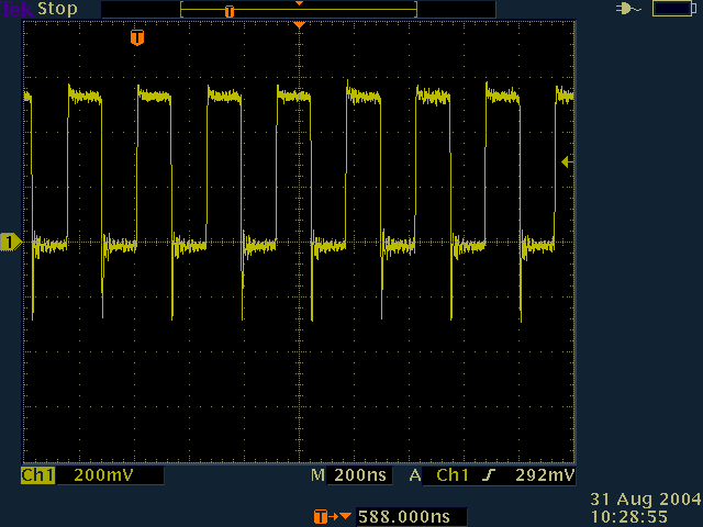
recv clock on timing board in gold box, 250ns period (4MHz):
recv data on timing board, immediately after running the testcam
program:
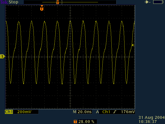
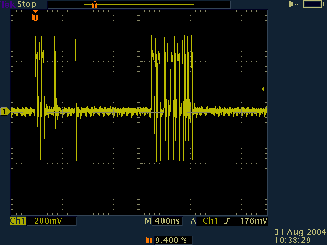
xmit clock on timing board (20nsec period, 50MHz):
xmit data:
enlargement of previous trace:
xmit data after pressing the reset button (which takes 0.7 seconds to
take effect):
enlargement of previous trace:
Mount computer
Analog, board 1
Channel 0 = RA
Channel 1 = Dec
Note: higher output numbers = lower output voltage +/- 10V
Encoder Card
Address: 0x20A
ICR: Valid index level will load the contents of the counter into the
Output Latch.
Active high index polarity.
Differential signals
10 MHz clock frequency
Counters not cascaded
Enable /BW (borrow) interrupt
Use IRQ 3
No wait state.
DIO Card, board 0
A0 - West Limit/ In
A1 - East Limit/ In
A2 - North Limit/ In
A3 - South Limit/ In
A4 - RA Amplifier Fault In
A5 - Dec Amplifier Fault In
A6 - E-Stop Tripped In
A7 - Dec Encoder Error In
C0 - RA Encoder Error In
B0 - RA Brake Out
B1 - Dec Brake Out
B2 - RA Heater Out
B3 - Dec Heater Out
Quick guide to rush
While not hardware as such, I'm including here a quick quide to some aspects
of rush, the Bourne-like shell that ROTSE uses.
rush is based on rc, an implementation of the Plan 9 shell for
UNIX. Authors are Byron Rakitzis and Tom Duff. See
here for
documentation.
Here are some examples of rush syntax:
rhelp # for help on ROTSE specific commands
path=($path /somewhere/else)
echo $path
lastFile=`{ls -t|head -1}
{sleep 60; echo Both commands run in the background}&
for(i in *.c){ls $i}
if(test -f /tmp/junk) echo /tmp/junk exists
while (){echo loop forever; sleep 10}
fn go { echo this is a function called go }
fn go # this deletes the function called go
rush reads the file ~/.rcrc at startup.
Processes that you start in rush are run as root.
Collimation of the secondary mirror
The secondary is flat, so only a tilt adjustment is necessary.
To assist with collimation, it is helpful to have an easy way to take
and display an image on the rotse computer. Here is one technique:
- Make sure that ds9, xpans, and xpaset are installed.
- Login as observer.
- Edit the ~/.rcrc file so that the path to ds9, xpans, and xpaset is
included in the command search path.
- Add the following functions to .rcrc:
fn minit {

# This function performs the initial setup, it should be
# run immediately after starting rush.

  rinit
  rmode manual
  pgrep -f xpans > /dev/null || xpans -p 14285 &
  pgrep -f ds9 > /dev/null || ds9 &
}

fn mdisp {

# Displays the most recent "junk" fits file.

  f=`{ls -t /rotse/data/3a1/*_junk_*.fit | head -1}
  xpaset -p ds9 file $f
}

fn mgo {

# Takes a 10 second exposure, and displays it.

  rexpose -w -t 10 -n junk
  sleep 3
  mdisp
}
- Start up a couple of xterms as user observer. Run "rmonitor" in one
of them. Start the rotse system with "killrotse -nob; killrotse -nob
-dam; allrotse.pl". Wait until the clam is open and the mount is
synced and has moved to the zenith.
- Start "rush". Type "minit" to initialise. A ds9 window should open up.
- Type "mgo" to expose for 10 seconds and display the result. Sometimes
the most recent image isn't displayed - try "mdisp" to fix this. You might
like to use FRAME, NEW in ds9 to put new images into another FRAME for
comparison.
- Focus using, e.g., "fmove -r 3.65". Positions are absolute and in
millimetres, although the documentation says relative in microns.
- Offset the focus by -0.65mm. This should give nice donuts as per
the image below.
- Position the telescope for convenient access to the secondary mirror
micrometers. E.g., "rmove -w -r 5 0 0 -d -80 0 0", if the LST is "5 0 0"
and you are at Siding Spring.
- Call the lower left micrometer A, and the lower right one B.
- Turning A clockwise moves the "sweet spot" (where the donuts are
perfect annuli) on the CCD roughly diagonally from top right to bottom
left. Turning B clockwise moves the sweet spot roughly horizontally from
left to right. 1/16 of a turn is enough to move the spot by about 0.5 of
the width of the CCD.
- Iterate until the sweet spot is in the centre of the CCD, as per
the following image:
(click on the image for the full-resolution view)
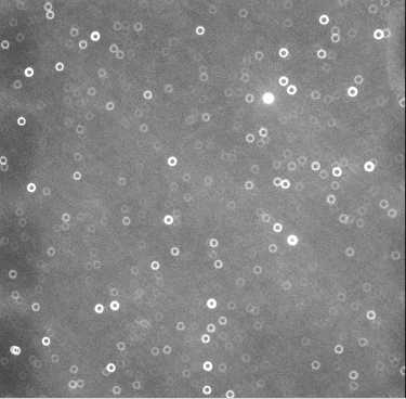
Note how the hollows in the centres of the stars all point towards the centre
of the CCD. The final adjustments are perhaps 5 degrees of rotation of the
micrometers.
Here are some instructions from Fang Yuan on how to update the focus
model:
- After you aligned
the mirror and find a reasonable good focus position, you need to put that
position into the focus model file.
- First of all, you should delete the
/rotse/data/pipeline/prod/focus_update.dat, which is a small adjustment
from mini-focus run. Run "rhup schierd", so the original focus model is in
use.
- According to /rotse/run/etc/schierd.conf on 3a, the current focus model
file is /rotse/run/etc/focusmod_060726.dat. You
may copy this into a new file, and modify the entry in schierd.conf.
Because we are not changing the focus model, the only number has to be
changed is the constant term, which is now 3.64202. The trick is to find
out the offset between the current model and the new good focus, and add
the offset to the current constant. Say, for a certain pointing, the focus
model calculate 3.5, and you find it to be 3.7, then you should put
3.64+0.2=3.84 as the constant.
To get what focus the current model gives, just point with "rmove -r ra -d
dec" in rush, while "rmove -r ra -d dec -n" will just move the mount but
NOT the focus.
-
After you've changed the focus model file, "rhup schierd" again. Then you
may point again with "rmove -r ra -d dec" to see if the focus comes out
good. It just needs to be close enough to the best focus, and mini-focus
runs will take care of the fine tuning.
Replacement of the Dec encoder tape
Most of the following images expand if clicked on.
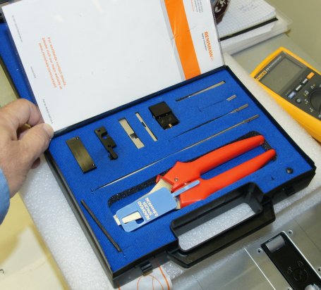
- Obtain a new piece of encoder tape, and borrow (if at all
possible) an encoder tape applicator (see image below). Cut the tape
to length with the supplied shears.
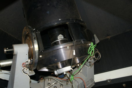
- Take off a side panel of the telescope
and release the focus cable from the Newport
controller box.
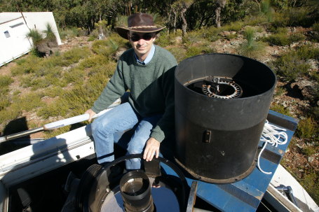
- Remove the top half of the telescope. It weighs perhaps 12kg, and
is an awkward, but possible, lift by one person. There aren't any
alignment pins, just unscrew the bolts and lift off, being
careful to clear the central optics tower. We lowered the
tube section over the side of the enclosure, but it is also possible to
lower it inside the enclosure.
- Attach weights to the telescope so that it is counterbalanced, and
can rotate freely through 360 degrees in declination. After this image
was taken, the optics were cleaned, and they came up perfectly.

- Remove the old tape by peeling it off, scraping the residual glue
with a sharp knife, and using a solvent (e.g., white gas, shellite,
Coleman fuel) to clean the disk. Then give the surface and the
surrounding area a thorough polish with 400 grade "wet and
dry". Finish with a careful clean with methylated spirits.

- Read the applicator instructions thoroughly. Attach the applicator
device
to the encoder mount. You will need to use the left-hand adaptor
plate.
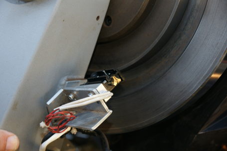
- The following photo shows the applicator guide in position, with
the new tape ready to apply. Note that there is very little leeway,
and you have to be careful not to bend the tape through too small a
radius of curvature. Attach the tape to
the disk when the telescope is pointing directly at the north pole (or
south pole for Northern Hemisphere ROTSE's) - this is a place that the
telescope can never point to once the top half is
reattached. Carefully rotate the telescope through 360 degrees,
slowly, and in one direction only. After all the tape is on, remove
the applicator and use a lint-free cloth and firm finger pressure to
securely attach the tape from the outside to each end.
- Collimate the secondary.
Vaisalla precipitation detector
The Vaisalla precipitation detector is a model DRD11A. The sensor
surface should be periodically cleaned with pure water and a soft towel
(mild detergent is allowed). Avoid static damage to the sensor. The
pinouts are as follows:
Red
|
+12VDC +/- 10% @ 260mA max, 25mA
with
heater off
|
Blue
|
Rain ~ON/OFF open collector
output; grounded when rain detected; 50mA max
|
Green
|
Heater OFF input; ground to turn
heater on; float to turn heater on; heater draws between 0.5 and 2.3W
|
Yellow
|
Analog out; 3V when dry; as low
as 1V when wet
|
White
|
Frequency output; 1500Hz
to 6000Hz
|
Black
|
Ground for analog components
|
Brown (or clear)
|
Ground for heater
|
Odds and ends for ROTSE-IIIa
Our ethernet hub was purchased in January 2004, and is a
M-EZ6508TX 1 SMC 8 port
10/100 Switch
EZ6508TX
$50.00
Shipping address for data disks to Michigan
Carl Akerlof
450 Church Street
2477 Randall Laboratory
University of Michigan
Ann Arbor, Michigan 48109
USA
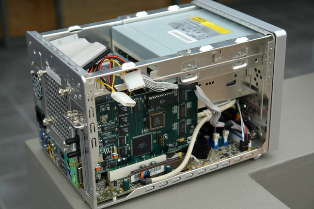
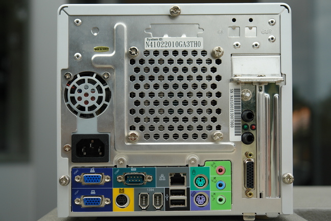
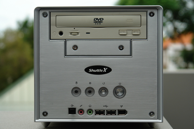
cam3a computer
cam3a is a Shuttle SN41G2 "barebones" small-form-factor PC, serial
number N41G00313D07060, system ID N41022010GA3TH0. The motherboard is a
FN41 V2.0. The BIOS is fn41s032 dated 2005/5/23. The CPU is a 1.9GHz
Athlon. 1GB memory. 200GB Seagate hard disk. The chipset is an NVidia
nForce 2, which means you have to download NVidia drivers for the
network, sound, and graphics. We are currently running Linux 2.4.32,
with a Redhat 7.2 underlying OS.
Back view of cam3a:
Front view of cam3a:
Showing the CCD controller card. There is barely enough room:
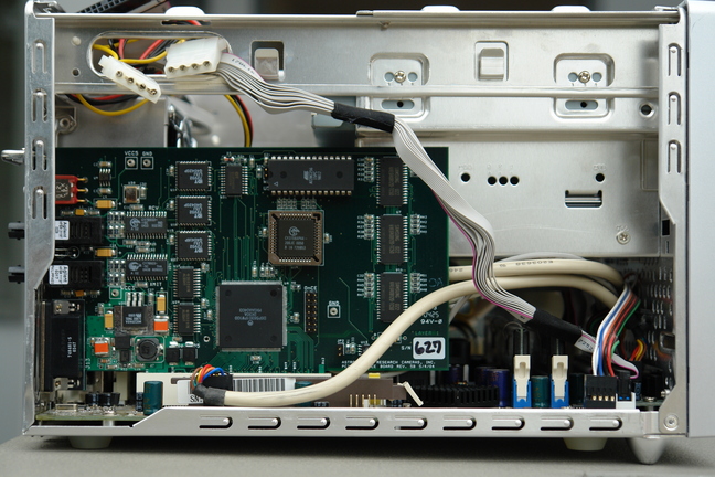
With the case open:
